 |
||
|
Obrigado a Julio Marchi pelo espaço cedido na MSX All |
||
Create animated displays for MSX screen 2 images.
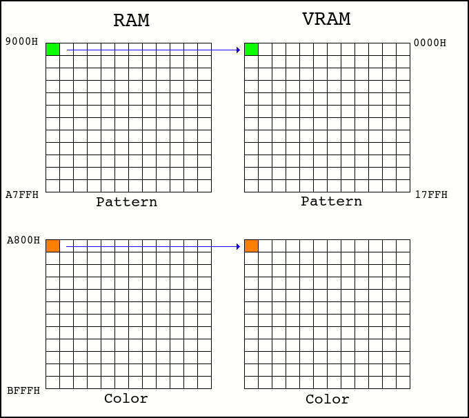
The display program first loads the image on the MSX's RAM, then it copies the data to the VRAM. Such thing give us the control on how to transfer the image data to the screen, making it possible to introduce some animation effects while loading the image on screen. We can load 1x8 or other size blocks (e.g.: 8x8 pixels) at time from RAM to VRAM. The order we load these blocks into the VRAM will give us the animation effect. We must take into account that MSX screen 2 data is composed by two tables: pattern and color, and it is strongly recommended that, for each block, we load the data from both tables together. See the next image. An 8x8 pixel block is transferred from RAM to VRAM, first reading the pattern table, then reading the color table. 
The order of the blocks copies from RAM to VRAM management is generally done by an Assembly program, once it is very fast. However, some animation effects can be extremely complex to be achieved through a program. In order to make the creation of animations easier, we use a map that contains each 8x8 pixel block loading order. This map contains pointers to the 1x8 pixel blocks in the RAM. By this way, all that the main display code has to do is to read the map in order to determine which block will be loaded. The following figure shows the structure of the image file. It is a binary, self-executing file, which contains the uncompressed pattern and color table data, an assembly code to read the map data and transfer the blocks to VRAM, and finally the map. 
Besides we are working with 8x8 pixels blocks, the addressing follows the screen 2 structure pattern, which is 1x8 pixels. In that case, the map will have addresses from &H0000 to &H17F8 (6144 blocks of 1x8 pixels), jumping by 8 (8x8 grouping). We need 2 bytes to represent these values, times 768 blocks of 8x8 pixels, resulting in 1536 bytes of map size. This addressing is relative, starting from position 0. The display programs will adjust this relative address to the beginning of both pattern and color tables. The next schema describes how the relative addressing is related to the MSX screen divided by 32 columns and 24 rows (8x8 pixels blocks). +----+--------+--------+--------+-----+--------+--------+ | | 00 | 01 | 02 | ... | 30 | 31 | +----+--------+--------+--------+-----+--------+--------+ | 00 | &H0000 | &H0008 | &H0010 | ... | &H00F0 | &H00F8 | | 01 | &H0100 | &H0108 | &H0110 | ... | &H01F0 | &H01F8 | | 02 | &H0200 | &H0208 | &H0210 | ... | &H02F0 | &H02F8 | | .. | .... | .... | .... | ... | .... | .... | | 23 | &H1700 | &H1708 | &H1710 | ... | &H17F0 | &H17F8 | +----+--------+--------+--------+-----+--------+--------+ The display programs allow us to introduce a delay between each block transfer, making some animations more noticeable. The delay can be created between the transfer of each block or a group of blocks (frame). The delay is identified in each map address value when we set its most significant bit. See the following example for VRAM block 0. +----------+-------+-----+-----+-----+-----+-----+-----+---------------+ | Address | Block | b15 | b14 | b13 | ... | b01 | b00 | Obs | +----------+-------+-----+-----+-----+-----+-----+-----+---------------+ | &H0000 | 0 | 0 | 0 | 0 | 0 | 0 | 0 | Without delay | +----------+-------+-----+-----+-----+-----+-----+-----+---------------+ | &H8000 | 0 | 1 | 0 | 0 | 0 | 0 | 0 | With delay | +----------+-------+-----+-----+-----+-----+-----+-----+---------------+The display time can be modified directly in the display programs. For that, checkout the programs' source code. When a value is read from the map, it is converted to RAM/VRAM pattern and RAM/VRAM color addresses. Also, the delay bit is removed. See the next example. E = MAP(pos) RAM_PAT = E + &H9000 VRAM_PAT = E RAM_COLOR = E + &HA800 VRAM_COLOR = E + &H2000 How to generate a map We can use the PCs to generate automatically the map. For that, we must create a 32x24 pixels image sequence containing the display progress. A program can be created to read these images and convert these sequence into the map. We read the images in sequence, always calculating the difference image from current and previous image. The resulting pixels are the new block pointers to be inserted in the map. 
So, we insert the new elements found in the map array. MAP.insert(new_blocks) The display maps have examples on how to create animations. |
||
