 |
||
| Menus | ||
Create animated displays for MSX screen 2 images.
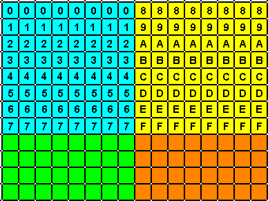
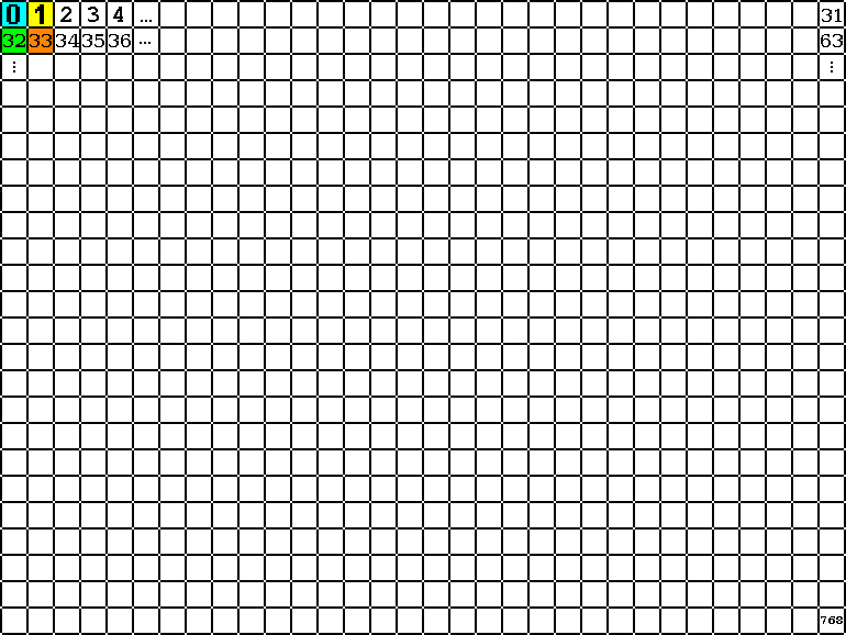
For developing screen 2 opening animations, it is necessary to understand the screen 2 architecture before. The screen 2 is a matrix with 256 columns and 192 rows, numbered from 0 to 255 and 0 to 191, respectively. Nevertheless, it has a particular way to store data. Let's see how. This screen mode groups 8x1 points, which are represented by two bytes. The first byte stores the foreground color and background color information and it is called color byte. The last byte store the pixels pattern and it is called pattern byte. In this byte, each bit 0 says that the pixel has the background color, whereas the bit 1 says that pixel has the foreground color. Let's see the next example.  The most significant bits (MSB) store the red color (code 6 or &B0110) for the foreground color, while the least significant bits (LSB) store the yellow color (code 10 or &B1010) for the background color. The next figure shows the correspondence between bits 0 and 1 from the pattern byte and the 8x1 pixels. By grouping 8x1 pixels in screen 2, we have 256 / 8 or 32 groups per line. For the whole screen, we have 32 x 192 or 6144 groups. As each group takes 2 bytes, we need 12,288 bytes to store the whole screen. The screen 2 video memory (VRAM) has two contiguous areas reserved to store screen data: the pattern table and the color table. The pattern table ranges from 0 to 6143 (or 0 to 17FFH), while the color table ranges from 8192 to 14335 (2000H to 37FFH). The next figure shows the correspondence between the first two 8x1 groups and these two tables.  As seen on the figure above, the 8x1 groups are arranged in vertical way. Nevertheless, eight 8x1 groups compose a greater set, resulting on a 8x8 pixels block called character. The next figure presents two characters. The first character (light blue rectangle) has the 8x1 groups numbered from 0 to 7. The second character (yellow rectangle) has the 8x1 groups numbered from 8 to 15.  The next figure shows how the characters are arranged on the screen. Notice the block from the previous figure overlapping the grid at the top-left.  Which is the value of the first line (8x1 pixels group) for the character 32 (green)? And the first line of the character 33 (orange)? If each character has 8 lines, then we may calculate the first line of a character in the following way: FLC = No_character x 8 According to that, the first line of character 32 is: FLC = 32 x 8 = 256 For the character 33, we have: FLC = 33 x 8 = 264 How to calculate the VRAM address from a single pixel Which are the memory positions used by the pixel (128,95)? Step 1- Which character this point belongs to? First we have to calculate the point into the character coordinate system. For that, convert the values using the following formula: cx = FLOOR(X / 8) cy = FLOOR(Y / 8)So, we have: cx = FLOOR(128 / 8) = 16 cy = FLOOR(95 / 8) = 11Now we can calculate the character number. For that, use the following formula: Ncharacter = cx + cy x 32So, we have: Ncharacter = 16 + 11 x 32 = 368 Step 2- Where is this character is located in the video memory? As seen on the previous section: FLC = 386 x 8 = 2944 Step 3- Which line from the character is this coordinate? The first line of the current character is: 11 x 8 = 88 The y-coordinate of the point is: 95 The character line is then: 95 - 88 = 7 Step 4- Calculate the line offset The memory address then is: 2944 + 7 = 2951 For the pattern byte, the address is 2951 (0B87H) For the color byte, the address is &H2000 + 2951 = 11143 (2B87H) |
||
